

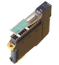
AS-Interface sensor/actuator module VAA-4E4A-KE5-ZEJQ/R
- Housing with push-in connection technology and mechanically coded terminal blocks
- Housing width 19 mm, installation in the switch cabinet on DIN mounting rail
- Selectable supply to the sensors: External or from the module
- Function display for bus, internal sensor supply, inputs, and outputs


Please note: All product-related documents, such as certificates, declarations of conformity, etc., which were issued prior to the conversion under the name Pepperl+Fuchs GmbH or Pepperl+Fuchs AG, also apply to Pepperl+Fuchs SE.
PDF 파일로 된 데이타 시트 다운로드:
데이타 시트 발췌: 기술 사양 VAA-4E4A-KE5-ZEJQ/R
| 제품 설명 |
|---|
| Cabinet module 4 inputs and 4 relay outputs |
| General specifications | ||
|---|---|---|
| Node type | Standard node | |
| AS-Interface specification | V3.0 | |
| Required gateway specification | ≥ V2.0 | |
| UL File Number | E223772 | |
| MTBF | 224 a | |
| Indicators/operating means | ||
| LED FAULT | Fault display; Red LED red: Communication fault or address is 0 red, flashing: Overload, internal input supply |
|
| LED INT | Internal input supply active; LED green | |
| LED PWR | AS-Interface voltage; green LED green: voltage OK flashing green: address 0 |
|
| LED IN | switching state (input); 4 LED yellow | |
| LED OUT | Switching state (output); 4 LED yellow | |
| Electrical specifications | ||
| Auxiliary voltage (input) | 12 ... 30 V DC PELV | |
| Rated operating voltage | 26.5 ... 31.6 V from AS-Interface | |
| Rated operating current | ≤ 35 mA (without sensors) / max. 230 mA | |
| Surge protection | O1 ... O4: Over voltage category II UEXT, Ue: overvoltage category II, safe isolated power supplies (PELV) |
|
| Input | ||
| Number/Type | 4 inputs for 3-wire sensors (PNP), DC | |
| Supply | from AS-Interface (switch position INT, default settings) or external UEXT (switch position EXT) | |
| Voltage | 21 ... 31 V DC (INT) | |
| Current loading capacity | ≤ 150 mA, overload- and short-circuit protected (INT) | |
| Input current | ≤ 5.6 mA (max.) | |
| Switching point | according to DIN EN 61131-2 (type 1) | |
| 0 (unattenuated) | ≤ 0.5 mA | |
| 1 (attenuated) | ≥ 2 mA | |
| Signal delay | < 1 ms (input/AS-Interface) | |
| Output | ||
| Number/Type | 4 relay outputs, normally open | |
| Supply | none | |
| Nominal load | ||
| Per contact | 2 A/30 VDC; 2 A/250 VAC For more information, see the "Galvanic Isolation" section |
|
| Per module | 8 A | |
| Control circuit | ≤ 11 mA per relay (from AS-Interface) | |
| Switching delay | < 10 ms (AS-Interface/contact) | |
| Usage category | DC-13 and AC-14 | |
| Switching | ||
| Mechanical | 5 x 10⁷ | |
| Electrical | 2 x 10⁵ (250 VAC, 2 A, cos φ = 0.4) | |
| Galvanic isolation | ||
| Input/Output | safe isolation, Rated insulation voltage 252 Veff | |
| Input/AS-Interface | Switch position INT: None Switch setting EXT: safe isolation, rated insulation voltage 92 Veff | |
| Output/Output | Basic insulation, rated insulation voltage 250 Veff, in phase | |
| Output/AS-Interface | safe isolation, Rated insulation voltage 252 Veff | |
| Directive conformity | ||
| Electromagnetic compatibility | ||
| Directive 2014/30/EU | EN 62026-2:2013 EN 61000-6-2:2005, EN 61000-6-4:2007 | |
| Low voltage | ||
| Directive 2006/95/EC | EN 60664-1:2007 | |
| Standard conformity | ||
| Galvanic isolation | EN 60664-1:2007 | |
| Degree of protection | EN 60529:2000 | |
| Fieldbus standard | EN 62026-2:2013 | |
| Electrical safety | IEC 61140:2009 | |
| Input | EN 61131-2:2004 | |
| Emitted interference | EN 61000-6-4:2007 | |
| AS-Interface | EN 62026-2:2013 | |
| Noise immunity | EN 61000-6-2:2005, EN 61326-1:2006, EN 62026:2013 | |
| Programming instructions | ||
| Profile | S-7.0 | |
| IO code | 7 | |
| ID code | 0 | |
| ID1 code | F | |
| ID2 code | E | |
| Data bits (function via AS-Interface) | ||
| D0 | ||
| D1 | ||
| D2 | ||
| D3 | ||
| Parameter bits (programmable via AS-i) | function | |
| P0 | Communication monitoring P0 = 0 monitoring = off, the outputs maintain the status if communication fails P0 = 1 monitoring = on, i.e. if communication fails, the outputs are deenergised (default settings) |
|
| P1 | Input filter P1 = 0 input filter on, pulse suppression ≤ 2 ms P1 = 1 input filter off (default settings) |
|
| P2 | Synchronous mode P2 = 0 synchronous mode on P2 = 1 synchronous mode off (default settings) |
|
| P3 | not used | |
| Ambient conditions | ||
| Ambient temperature | -25 ... 60 °C (-13 ... 140 °F) | |
| Storage temperature | -25 ... 85 °C (-13 ... 185 °F) | |
| Relative humidity | 85 % , noncondensing | |
| Climatic conditions | For indoor use only | |
| Altitude | ≤ 2000 m above MSL | |
| Shock and impact resistance | 15 g, 11 ms in 6 spatial directions, 3 shocks 10 g, 16 ms in 6 spatial directions, 1000 shocks | |
| Vibration resistance | 0.35 mm 10 ... 57 Hz , 5 g 57 ... 150 Hz, 20 cycles | |
| Pollution degree | 2 | |
| Mechanical specifications | ||
| Degree of protection | IP20 Installation in an enclosure with a minimum protection class of IP54 required |
|
| Connection | Removable push-in terminals rated connection capacity: rigid: 0.20 mm2 ... 1.5 mm2 flexible (without wire end ferrule): 0.20 mm2 ... 2.5 mm2 flexible (with wire end ferrule): 0.25 mm2 ... 1.5 mm2 |
|
| Material | ||
| Housing | PA 66-FR | |
| Mass | 125 g | |
| Dimensions | ||
| Height | 100 mm | |
| Width | 18.9 mm | |
| Length | 124 mm | |
| Mounting | DIN mounting rail | |
Classifications
| System | Classcode |
|---|---|
| ECLASS 13.0 | 27242604 |
| ECLASS 12.0 | 27242604 |
| ECLASS 11.0 | 27242604 |
| ECLASS 10.0.1 | 27242604 |
| ECLASS 9.0 | 27242604 |
| ECLASS 8.0 | 27242604 |
| ECLASS 5.1 | 27242604 |
| ETIM 9.0 | EC001599 |
| ETIM 8.0 | EC001599 |
| ETIM 7.0 | EC001599 |
| ETIM 6.0 | EC001599 |
| ETIM 5.0 | EC001599 |
| UNSPSC 12.1 | 39121535 |
Details: VAA-4E4A-KE5-ZEJQ/R
Product Documentation: VAA-4E4A-KE5-ZEJQ/R
| Brief Instructions | 언어 | 파일 타입 | 파일 크기 |
|---|---|---|---|
| Instruction leaflet / Beipackzettel | ALL | 1483 KB |
Design / Simulation: VAA-4E4A-KE5-ZEJQ/R
| CAD | 언어 | 파일 타입 | 파일 크기 |
|---|---|---|---|
| CAD 3-D / CAD 3-D | ALL | STP | 19087 KB |
Approvals: VAA-4E4A-KE5-ZEJQ/R
| Certificates | 인증서 번호 | 언어 | 파일 타입 | 파일 크기 |
|---|---|---|---|---|
| AS-Interface | 123601 | ALL | 117 KB | |
| US CA UL | E223772 | ALL | LINK | --- |
| Declaration of Conformity | ||||
| EU Declaration of Conformity (P+F) / EU-Konformitäterklärung (P+F) | DOC-1953B | ALL | 115 KB | |
| UK Declaration of Conformity (P+F) | TDOC-7013_ENG | ENG | 172 KB | |
관련문서: VAA-4E4A-KE5-ZEJQ/R
| Accessories | ||||||
|---|---|---|---|---|---|---|
|
||||||
|
||||||
|
||||||
|
||||||


This free PDF white paper compares the different TCP-based communication protocols (AMQP, OPC UA, MQTT, REST API) that have found their way up and are considered the enablers of IIoT and Industry 4.0. Get your free download now!
AS-Interface Switch Cabinet Module KE5 – Simple Handling and Improved Manageability
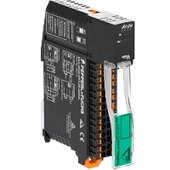
The unique housing design of the new KE5 switch cabinet module enables distinct visibility and simplifies mounting, wiring, and maintenance inside switch cabinets and junction boxes.


페펄앤드푹스코리아(주)
서울특별시 서초구 서초대로88
6층 (유니온빌딩)
06673 대한민국, 서울 특별시
대한민국
info@kr.pepperl-fuchs.com
 +82 2 34819494
Pepperl+Fuchs는 세계 자동화 시장에서 전자기 센서 및 컴포넌트 제조 및 개발의 선두주자입니다. 지속적인 혁신, 오래토록 변치 않는 품질 및 꾸준한 성장이 지난 70년 동안 계속적인 성장을 보장하였습니다. Pepperl+Fuchs의 전세계에 6,300명의 임직원을 보유하고 있으며, 독일, USA, 싱가포르, 헝가리, 인도네시아 및 베트남에 제조 시설을 가지고 있으며, 대부분 ISO9001을 획득하였습니다.